Vibration analysis project
In this section, you'll use Fusion 360's ability to do Finite Element Analysis (FEA) to simulate the mechanical response of your plate to a vibrating force.
Finite Element Analysis
Finite Element Analysis is a numerical technique (=software running on a computer) used to model a structure and calculate its response to some sort of stimulus. Some examples:
- Depending on the material's density, each node is modelled as a point mass.
- Depending on the elastic characteristics (stiffness, shear response...) of the material, the lines between the nodes are modelled as springs of a determined stiffness with a characteristic damping (friction).
- Set the material of your plate. Select the entire object by clicking and dragging to include all of it. Then right click on it and select Physical Material. In the dialog box that opens, find just plain Aluminum and click and drag it onto the object. Then you can close.
- Indicate your clamping point: We want the clamping point--well, it's more like a clamping area--not to move even when the rest of the plate is allowed to flex. In the lingo of FEA, this is "constraining" part of the of surface. To "place a constraint" we'll pull up a small portion of the surface, so that it's a separate surface from the rest of the plate. This is a bit of a kludge to allow us to select all the rest of the surface to vibrate freely.
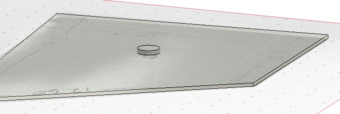
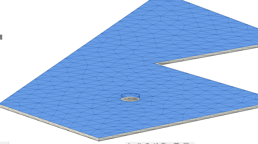
- Draw the location of the clamp point as a circle: First select the top surface of the plate by clicking on it once. Then Create | Sketch and select the Circle | Center-Diameter-Circle. Click to place the center and then move the mouse to set the diameter to 5 or 10 mm. Then FINISH SKETCH.
- Zoom in with the mouse wheel and select the inside of the circle
- Now Extrude the surface up by a Distance of 1 mm, so that you have what looks like a circular disk sitting on the surface of the plate.
- Now we can solve for the vibration modes.
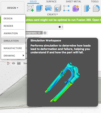 Drop down the DESIGN menu and select SIMULATION. Then in the dialog, select Modal Frequencies and click Create Study.
 Click the menu box
which allows you to manage settings. Set the number of modes to 12. Click Create Study.
Click the menu box
which allows you to manage settings. Set the number of modes to 12. Click Create Study.
- Select the little circle surface. Then under CONSTRAINTS, select Structural Constraints. Accept the default that constrains that face in all three directions and just click OK. You should see a little padlock appear on the circle face.
- Choose SOLVE | Generate mesh. Cool.
- Choose SOLVE | Solve. In the dialog, do it On Cloud and click Solve 1 Study at the bottom of the menu.
- Name the file you will create.
- Wait while it carries out a very sophisticated calculation.
- View and record the results.
- Choose RESULT TOOLS | Report Give it a name and put it in a folder that you can remember! You'll end up with a single .html file (like this) that has the images embedded in the file: A completely self-contained file.
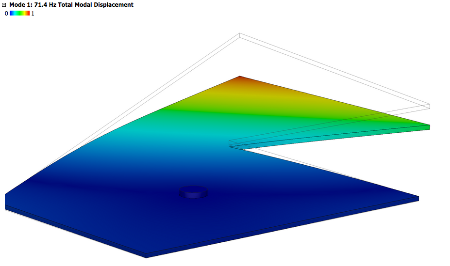
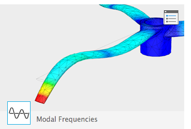
Usually the dark blue color indicates the nodes, the parts of the plate that are still, while the other colors indicate portions of the plate that are moving.
Compare the modelled results with the modes that you found
You should be able to pair most of your measured modes with a calculated mode. But some of the measured modes will be beyond the set you have calculated. And some of the calculated modes will be difficult to excite and so you may not have found them. See how many you can pair up.
Note any significant discrepancies in the frequencies. Try to figure out why they occurred.
Modify the plate and repeat
Now you'll modify your plate, and then repeat both the measurements and the calculations with the modified plate.
- Plan a cut or several cuts to remove small parts of the plate.
- Try not to remove too much or weaken it too severely. You want the modes to be largely the same but have changed frequencies that you can easily compare.
- Plan cuts that you think will affect some modes much more than other modes.
- Don’t break the symmetry of the plate. If you cut on one side, make a symmetric cut on the other
- Write out your predictions as specifically as possible.
- For each mode, indicate qualitatively how you expect the frequency to change.
- Do compare as much as possible: mode X will be somewhat lowered, mode Y will be greatly raised, mode Z will be unaffected.
- Make the modifications to your plate.
- Find the actual modal shapes and frequencies by using the Electronic Laser Holography System with your modified plate.
- Make the same modifications to our Fusion 360 model
- Find the modal shapes and frequencies using Fusion 360’s Finite Element Analysis Solver
Modify your plate
Here's how you can modify your design in Fusion 360, rather than starting from scratch again:
To remove a section,
- Start a sketch. Click on the top surface of the plate, then under Sketch select the line tool. Draw the line and then finish the sketch. Now your top surface is divided into two parts.
- Select the part of the surface you want to eliminate. Then under Modify, select the Press-Pull tool.
- Press it down through the object. The dialog box guesses correctly that the operation you want is a cut. Click on OK and that section is gone.
 We could push on one part of piece. We'd like to know things like: Will it break? How much does it bend? What are the internal stresses (forces)--that is, where is it most likely to break? Or where should we add more material so it *won't* break?
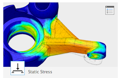
 We could heat one part of a piece. We'd like to know things like: What are the temperatures of other parts of the structure? How much might different parts of the piece expand or contract?
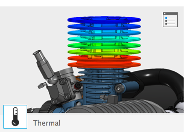
 We could shake a piece with a sinusoidal force at different frequencies. We'd like to know things like: what are the frequencies at which the plate resonates? For a particular resonant mode, what parts of of the piece are moving quite a bit or not so much? (Those might be places which are more likely to wear or break.) What if we clamp certain parts of the piece so that they can't move?
That last case is what we're interested in!
The software calculates a "mesh" to model the actual piece with a simplified, and "finite" network of lines and nodes (meeting points of the lines), which have the shape of the real-life piece.
Springs and masses obey well-defined differential equations. The solutions to these equations are not particularly difficult. You have probably already studied in General Physics how a single mass attached to a spring behaves?! But the many masses, springs, connections in different directions, and eventually constraints present a significant accounting challenge. Fortunately this is exactly what computers are good for!
Using Fusion 360 for Finite Element Analysis
I'm assuming you have already installed Fusion 360, and that you have already created a 3d drawing of your plate. Since Fusion 360 stores all its files in the cloud, you should see your plate somewhere on the left side of the screen. Pull up that drawing.