Lab 01
Pre-Lab Assignment
- Work on #2 of lab and see how much you can do before lab.
Try to get a blink program running.
Make some simple change to it.You'll hand in your lightly modified, commented blink program.
Don’t go further than that. You can wait until the lab to try attaching the 9V battery.
- Start thinking about possible projects.
Lab feedback
Coding
- Some of you wrote programs to light up the LED(s) in Morse code sequences. Instead of "hard coding" the waiting times, you could make variables with descriptive names. This also gives you the option of changing all the delays for the different parts of a letter at a later time, in one spot.
Also, notice how I've compressed some repeated things with more than one command on a line. Hey, as long as you separate the commands with "
;" this will work!int dash=2000; \\Light the LED for 2 seconds to indicate a Morse code "dash" int dot=500; \\Light the LED for 1/2 second (500 mSec) to indicate a "dot" int dark=200; \\Time to wait (0.2 seconds) between flashes ... \\Letter m is dash, dash digitalWrite(12, HIGH); delay(dash); digitalWrite(12, LOW); delay(dark); digitalWrite(12, HIGH); delay(dash); digitalWrite(12, LOW); delay(dark);
Lab 01: Arduino and Soldering
- Introduction to Lab Space
- Station equipment, tools, counter space, neatness expectations (how to leave things)
- Introduction to Arduino IDE (integrated Development Environment)
- Start the Arduino IDE program (without having any Arduino connected). Look around in the menus. The programs you write are called sketches and so you can save them in your sketchbook.
- Serial Connection. Open the tools menu and check for the Serial Port which should be grayed out because the program did not find any Arduino connected. Now plug in the Arduino using the USB cable. Close and open the tools menu and you should now have a serial port. Make sure it is selected.
- Help. Under help click on Reference. This takes you to the Arduino Language Reference Page. Explore a bit here and see how useful this can be. It is a great resource provided you have an internet connection. Otherwise there is no help.
- Load the Blink example (File | Examples | 01Basics | Blink). Then upload it to the Arduino using the Upload button. At the completion of the upload, the Arduino should start running this program and the LED should blink.
- Change the program somehow and upload the new version. The old program will still be running on the Arduino until near the end of the process when the new one is actually uploaded. As part of the process, your program must first be compiled from C code into machine code. The checkmark button is a way to just compile the program to check for syntax errors but not to upload it.
- Try disconnecting the USB cable and running it from a 9 volt battery so it is completely independent.
- Wiring a simple LED circuit
- Label your Arduino and Board and Kit
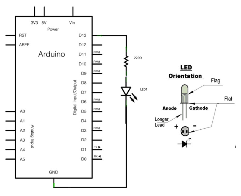
- Get an LED from your kit (any color) and connect it to D13 of the Arduino using your little breadboard. Be sure to put a 560 ohm (Green Blue
Brown Gold) resistor in series with the LED. This is a similar schematic but with a 220 ohm resistor (which you don’t have):
- Show off your new circuit. You actually built that and programmed it!
- Now get creative in the time left for this section. Add more LEDs using different digital outputs. Turn them on and off in some interesting pattern. Get it working nicely and show your instructor.
Turn in the following (each of you individually): Draw a neat schematic on clean paper -or- draw it in Notability. Print out or save a copy of your well commented program. Upload your files, or pictures of your papers to Moodle.
- Soldering a Shield
- Watch the soldering demonstration.
- Solder part of the shield as you are instructed. There are directions for how to assemble and solder the shield at:
Several things that are not in the instructions:
- You'll use the stacking headers rather than the two-sided headers in the instructions. The stacking headers have pins coming out of the bottom, but have sockets on top, instead of pins.
- Along the top of the LCD shield board, you'll use 1 10-pin and 1 8-pin stacking header. Along the bottom of the shield, you'll us 2 6-pin stacking headers.
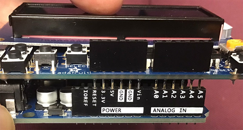
There are actually 8+6=14 sockets along the bottom of your Arduino board. Your shield will *not* connect with the leftmost blank and IOREF sockets, and that's OK:
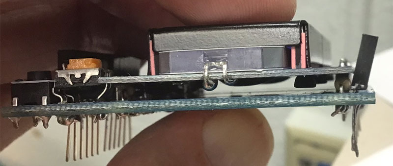
- There's not quite enough room to fit everything between the two rows of stacking headers. As shown below, you may need to put the top row of stacking headers in at an angle, and after soldering things, bend the pins so that they point down perpendicularly to the LCD shield board.
- Have an instructor inspect your solder joints
- Play around a bit soldering other kinds of things like wires or switches.
- Wash your hands before you leave if you wish to stay smart! (There is a little lead in the solder. While you are unlikely to breath any significant amounts in, some will be on your fingers. Washing your hands will make it unlikely that any is transmitted to that finger-licking good chicken you eat later on, avoiding any possibility of the effects of lead poisoning.)
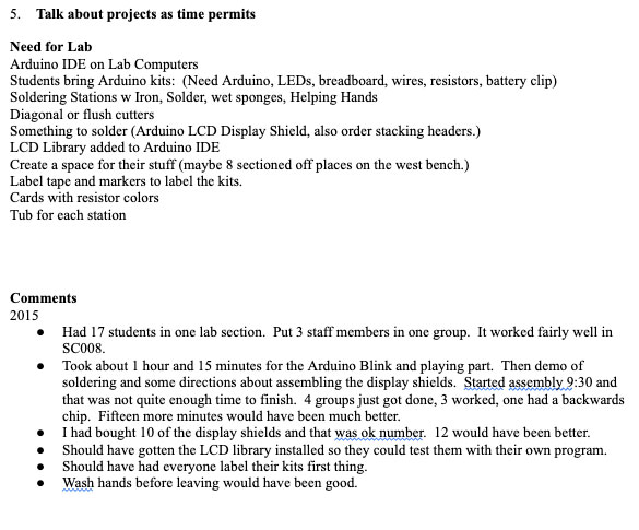
- Talk about projects as time permits
- Arduino IDE on Lab Computers
- Students bring Arduino kits: (Need Arduino, LEDs, breadboard, wires, resistors, battery clip)
- Soldering Stations w Iron, Solder, wet sponges, Helping Hands
- Diagonal or flush cutters
- Something to solder (Arduino LCD Display Shield, also order stacking headers.)
- LCD Library added to Arduino IDE
- Create a space for their stuff (maybe 8 sectioned off places on the west bench.)
- Label tape and sharpies to label the kits. gotten the LCD library installed so they could test them with their own program
Comments
2015
- Had 17 students in one lab section. Put 3 staff members in one group. It worked fairly well in SC008.
- Took about 1 hour and 15 minutes for the Arduino Blink and playing part. Then demo of soldering and some directions about assembling the display shields.
- Started assembly 9:30 and that was not quite enough time to finish. 4 groups just got done, 3 worked, one had a backwards chip. Fifteen more minutes would have been much better.
- I had bought 10 of the display shields and that was ok number. 12 would have been better.
- Should have gotten the LCD library installed so they could test them with their own program.
- Should have had everyone label their kits first thing.
- Wash hands before leaving would have been good.