Lab 03: Loading and Driving (a motor)
In today's lab you'll experiment with generating square waves and pulse-width-modulated (PWM) square waves. You'll use these to drive LEDs: With the same frequency, a longer duty cycle should result in a brighter light. You'll experiment with driving simple DC motors.
Pre-Lab Assignment
Create a physMenu that has the following menu items added to it:
- Squarewave output with adjustable frequency.
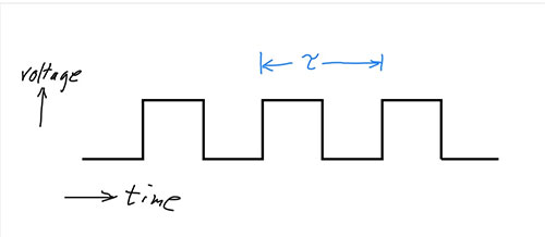
The period, $\tau$, of a time-varying signal is the number of seconds in one cycle. The frequency, $f$, is the number of cycles/second. (1 cycle / second = 1 Hz). So, looking at the units, it hopefully makes sense that: $$\tau = 1/f.$$- Create a function and add it to the menu to output a 1 kHz (1000 cycles per second) squarewave on one of the output pins. This can be done by repeatedly setting an output pin high and low with a very short delay after each. Use the
delayMicroseconds()function. (In the IDE, go to Help | Reference for more info.) - Next, modify things to make the frequency of your squarewave adjustable: Copy and modify the
setValue()function in your physMenu. That function allows you to modify a global variable named somenumber using the arrow keys. Make a new global variable, named for your new purpose. And have your function change the frequency by more than just $\pm$1 Hz for each button press.
- Create a function and add it to the menu to output a 1 kHz (1000 cycles per second) squarewave on one of the output pins. This can be done by repeatedly setting an output pin high and low with a very short delay after each. Use the
- Pulse Width Modulated output (PWM).
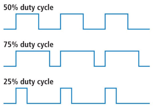
Several of the Arduino pins allow you to generate a square wave with a variable duty cycle: You can change the fraction of the cycle that the signal is HI.
Sparkfun
All of the signals picture above have the same frequency, but varying duty cycles.You'll use the
analogWrite()function to do this. See the documentation: Note that you won't have control over the overall frequency, but the different analog output pins have different frequencies.This is a 'higher level' control of a waveform, meaning you don't have to manually write all the code to make the voltage go up and down. You'll *only* control the duty cycle.
A good way to code this is, again, to modify a copy of the
setValue()function to adjust a global variable (again, make sure to pick a descriptive name) and display the value.Instead of adjusting up or down by one, have it adjust by $\pm$8 and have it start with a default value of 128 (the middle of the range of 1 to 256). Somewhere in the loop, have it do an
analogWrite()of this new variable to one of the PWM-enabled digital outputs of your Arduino Uno board.. That will produce the desired pulse waveform on that pin.
To hand in your pre-lab, upload or copy-and-paste just the new subroutines that you wrote for your physMenu.
Lab 03: Loading and Driving
- Squarewave Output Driving LED (35 min)
In the first part of the Pre-lab you made the voltage go up and down by setting a pin (for example, pin 2) HI and LOW, and had a way to adjust the frequency.
- Carefully put an LCD shield on one of your Arduinos.
- Using your breadboard, connect the pin you used (for example, D2 below) to the LCD, through the resistor.
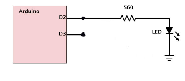
- Run your square wave subroutine with a frequency of 500 kHz. The LED should light up (and perhaps flicker) but not as bright as usual. What should be the duration of the high and low parts of the cycle be for this frequency?
- Look at the digital output (connect your probe where the signal comes out of the Arduino) with the oscilloscope. Does it look like a squarewave? Is it truly a 50% duty cycle squarewave?? What happens when you change the frequency? Show your instructor and confirm that your menu program with new subroutines worked correctly. (If your LED is not lighting up at all, you might change the resistor to something lower, like 200 ohms.)
- Take a picture of your scope trace for your note. What might be causing the problem?
- Is it the HI level or the LOW level which has a different delay that what you programmed and what might be the cause?
- Try changing the program to test your hypothesis. Record your hypothesis, how you tested it, and what the result was.
It seems that it is staying low longer than programmed. Apparently because of checking the button status.
- Look at the Arduino output with the oscilloscope while you connect and disconnect the resistor and LED. Can you see the effect of this load on the output? This is due to the output resistance of the Arduino. More on this in a bit.
- PWM Output Driving LED (25min)
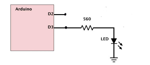
Connect your resistor and LED to the pin you programmed (shown here as D3) for PWM output in the prelab.
- Look at the output on the scope. Vary the duty cycle. Show your instructor and confirm that your program is doing what you expect.
- What happens to the output of the Arduino if you leave this menu function and go back to the main menu and then run some other menu function? Is this good?
- Set the duty cycle to 128 which should be 50%. What is it on the scope? (Include a picture of your scope trace.)
- Arduino Output Resistance Measurement (20 min)
Still looking at the PWM output, let's be more quantitative about the Arduino output, and figure out what the Thevenin-equivalent internal resistance of the Arduino is.
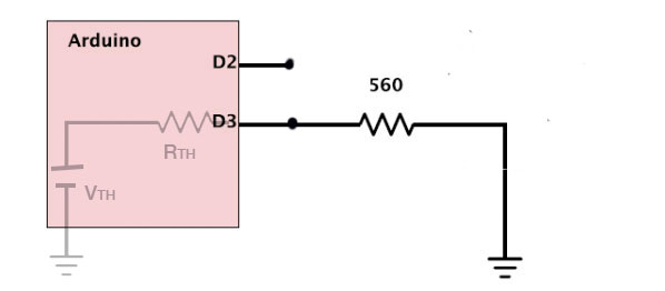
- With no circuit / no load between the Arduino pin output and
ground, measure the signal at the Arduino output with your probe.
This is the open-circuit or Thevin-equivalent voltage of the
Arduino.
- With no load, there's no path to ground from the output so no current flows.
- If no current flows through the resister $R_{TH}$ then there's no voltage drop across $R_{TH}$.
- So, the voltage at the output (right side of $R_{TH}$) is the same as $V_{TH}$ (which is on the left side of $R_{TH}$.
Justification:
- Now, take your LED out of your breadboard, and use just the 560 ohm resistor and connect it from the Arduino output to ground. Thus you are putting a total load of 560 ohm the output. Compare the Arduino output with this resistor connected vs. disconnected to see the effect of this load. You should see the output drop a bit when you connect the resistor. Look at the high part of the output cycle and record how much it drops when you attach the resistor.
- Thinking of the Arduino as a Thevenin device, use the measurement
you just made to calculate the internal resistance of the Arduino (as
seen through your chosen pin).
With a load resistor, $R_\ell$ the two resistors form a voltage divider. The voltage across the load resistor is given by: $$V_\ell = V_{TH}\cdot\frac{R_\ell}{R_{TH} + R_\ell}. $$ Use algebra to solve for $R_{TH}$.
The result is: $$R_{TH}=R_\ell\cdot\frac{V_{TH}-V_\ell}{V_\ell}.$$ - Repeat this whole procedure with a 100 ohm resistor instead of the 560 ohm resistor. Now you should see a bigger effect but the answer should be similar (and more accurate). Do not try any lower resistance, you could destroy the Arduino output.
- With no circuit / no load between the Arduino pin output and
ground, measure the signal at the Arduino output with your probe.
This is the open-circuit or Thevin-equivalent voltage of the
Arduino.
- Use a MOSFET to drive a DC motor (30 min)
Wire up the circuit below on your breadboard. It uses a MOSFET to control a DC motor. This circuit is shown connected to digital output D3 which is where you (may) have programmed your PWM signal to come out.
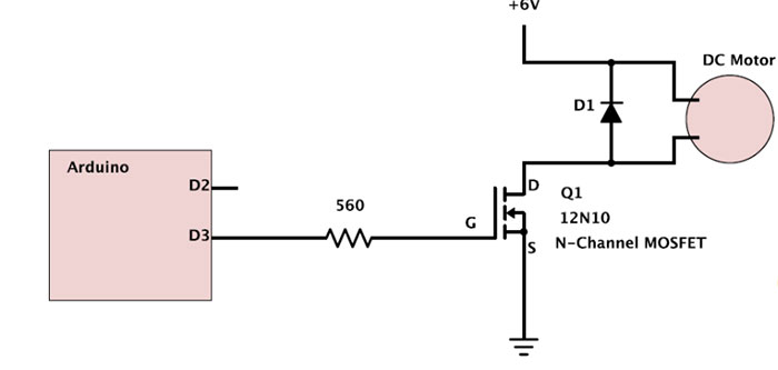
The diode D1 is the 1N4001 rectifier diode.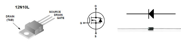
You'll use a separate power supply (where it says "6 V") for the motor. Turn the power supply on and set its maximum voltage to 6V. When you set the "current" you're actually setting a maximum current. Set that fairly high (500 mA??) for now.Your power supply will need to share a ground connection with the rest of the circuit. IMPORTANT: DO NOT connect the green terminal to ground! On all the power supplies, you'll connect the BLACK terminal to GND.
Also, DO NOT connect the power supply voltage (should be 6V) to any Arduino power lines.
Write down your observations as you work through the steps below.
- Try varying the duty cycle and observe the effect. Test for torque (by squeezing the motor shaft or otherwise slowing with a finger anything attached to the shaft as it rotates) as well as noting the speed.
- Try varying the voltage of the motor supply but do not go over 12V or so and at the higher voltages keep the duty cycle much less than 100%. Is there any clear difference between varying the duty cycle and varying the voltage?
-
Notice the diode across the motor output. It looks like this will
do nothing but it is important to include for protection. The coils
in the motor have inductance which means that current through them can
not change abruptly. So each time the FET is on briefly and conducts
current through the motor, then it turns off to stop the current. But
when the FET turns off, current keeps flowing through the motor coils
(current can not change quickly) and charge piles up at the point (D)
between them causing the voltage to climb to very high levels
(destroying the FET) unless there is somewhere else for the current to
go. The diode conducts when the voltage at D is higher than the power
supply voltage.
Try putting an LED in parallel with the diode (pointing the same *wrong* way (long lead is the lower one in this case). Describe what you see the LED doing.
- Look at the drain (D) with the scope. Take a picture of the waveform and label the different sections. You should be able to see when the FET is turned on (which means it is like a switch that is closed so lots of current can flow and there is essentially no voltage across it). Also note when it is off. Why isn't the voltage just equal to the +V value here? You should also see the spike that the diode tries to prevent. (Do not remove the diode, you might destroy the FET.)
- [optional] Try powering the Arduino from a 9V battery (disconnect the USB). This should work fine. Then try getting the motor power also from the same 9V battery. (use the Vin pin) The Arduino takes any battery voltage from 6-12 and converts it to 5V for its own use and also gives you that 5V supply for your circuit. But there is also a $V_\text{in}$ on the Arduino which just gives you a convenient place to connect something to the (9V) voltage you are feeding in from the battery. So connect this to your motor. This is a bad idea and might even fail but try it anyway. Look at the 9V power and see how messed up it is. Try loading the motor (squeeze the shaft a bit to make it work harder). Look also at the Arduinos 5V supply. Do you see why this is a bad idea?
- [Optional] For a still worse idea, drive the motor directly from the 5V supply. Now the motor load is directly affecting the logic supply that the microcontroller uses. Look at the 5V supply while the motor is working hard and describe it with colorful language.
So motors and other higher power devices are almost always powered from a different supply than the one used by the microcontroller. They only share the ground connection in order to have a common reference. Explain why this is done.
MOSFETs
The 12N10 MOSFET that we're using is an N-type enancement mode device. (Video and transcript about how these work.)
When $V_{GS}$ is zero, no current flows from the source to the drain.
The device *just* starts to conduct when $V_{GS}$ exceeds the threshold voltage...