Lab 04 Servos and Relays
The motors we worked with last week receive a number of pulses to make them move. But if you want to move them to a precise position, you have to set up your own system for initializing them, and counting the pulses to move them to a precise location. You also have no certainty that the pulses you sent to the motor actually resulted in motion. So, for more precise positioning we usually resort to...
Servo motors
A servo motor includes in one package:
- a motor
- some sort of sensor or encoder that can give position (and speed) feedback
- driver electronics and a power supply may also be included, such that all that must be supplied is a signal indicating the desired position of the motor.
The servo library is a set of functions, packaged as an C object that make it very easy to use servos.
At the top of your sketch you must #include <...> the header file, *.h, for the library. No need to install it, it's already part of the default Arduino IDE installation.
Objects in C: In the physMenu code, you included a header file and then created an m 'object' or 'instance' of the physMenu object with something that looked like a variable declaration. And indeed, it's up to you to call your object whatever you want.
To work with two servo objects, you would have lines like these at the top of your sketch (before your startup() subroutine):
// include the servo library
#include <Servo.h>

// create a servo object named 'myblueservo'
Servo myblueservo;

// ... and another one named 'myredservo'
Servo myredservo;
Then somewhere in your setup() you must tell each Servo object what pin to work with and optionally give the pulse widths for 0 and 180 degrees.
void setup() {

  // set up 'myblueservo' to work with pin 9
  myblueservo.attach(9);

  // set up 'myredservo' to work with pin 5
  // and let it be known that the pulse widths for
  //   0 and 180 degrees are
  //   520 and 2100 microseconds, respectively.
  myredservo.attach(5,520,2100);
Now in your main loop, you can use the Servo object functions write() or writeMicroseconds() for each servo to move it to a new position.
// set blueservo to 90 degrees
// this should be the midpoint of its range
myblueservo.write(90);

// sets red servo to 180 degrees
// (by outputting a pulse of 2100 microseconds)
myredservo.write(180);

// sets the blueservo pulse width to 1200us
// this should be about 60 degrees
myblueservo.writeMicroseconds(1200);
Maintaining a position: Servos must have a pulse sent to them regularly if you want them to actively hold their position. This is taken care of by the write function with a lot of code behind the scenes using timers and interrupts.
What this means is that when you execute a write(100) the Arduino will output a continuous stream of pulses of the corresponding width until you write some other value. So the motor will hold the position until you change it.
If you want to let go and turn the motor off, you have to use the detach([pin]) function.
Pre-lab assignment
-
ServoMove()Make a physMenu subroutine that allows you to use the display shield buttons to control a servo. Using the Arduino servo library and the
writeMicroseconds()function, write a menu function that allows you to control a servo by pressing the up and down buttons. Pressing a button should increase or decrease the displayed pulsewidth and move the servo to the new position. Make it adjust by increments of 25 microseconds. Sprinkler()Make a servo move like a lawn sprinkler. Write a program/function that uses the
write()function in the servo library that uses angles instead of microseconds. Make the servo sweep like a lawn sprinkler that gradually moves (tick, tick, tick…) in one direction until it reaches the limit and then rapidly (tsktsktsktsk...) moves back to the beginning and then starts over again. Make the speed of the whole process variable.
Lab 04 Servos and Relays
- Servos (50 min)
- Your instructor has a supply of servos and arms (called "horns" in servo lingo) that can be attached to the shaft. Attach one and play with your servo using your first program that just sends pulses of an adjustable length. When you get it moving appropriately in response to your program, make sure everyone in the lab knows how awesome you are! Then, draw a diagram of the circuit you're using.
- Play around some more. You know that a pulse train of 1500 microseconds width should place the motor in the middle of its range. Try larger and smaller pulse widths and see if you can find the smallest and largest pulse widths. Be careful here, if you put in a value that's beyond the limit, it will just go to the limit. You need to find the value that just gets it there. What are these maximum and minimun pulse widths, and do they correspond to an overall range of about 180 degrees?
- What happens if you send pulses outside the normal range of your servo? In other words, if your servo seems to respond to pulses in the range from 500 to 2500 $\mu$s, what does it do if you give it pulses of 300 or 3000 $\mu$s? Look at the pulses on the oscilloscope. Are they really exactly the width you set in your program?
- Try out your lawn sprinkler program. If it is not already, change the code so the return to the beginning happens all in one step rather than a bunch of quick little steps. How does the servo behave when it gets this one signal to move back to the beginning? Does it move instantaneously? There is a rating called the slew rate given in degrees per second that is relevant here. Try to make a rough determination of the slew rate of your servo.
- (If time permits and if different servos are available) Try a different servo from among those provided and see what is different about it. Mechanical range, pulse range, slew rate, are a few of the things you might easily compare. The most important differences are torque, size, and weight.
- Solid State Relay (40 min)
Do a short demonstration using the SSR boxes to turn a lamp on and off, using the pin of your choice from your Arduino. Anything from about 2 to 6 V across the red and black wires will turn on the relay. Unscrew the box to see what looks like an IC inside with 4 connections. Put it back together. At 2V the input will draw about 7mA but it does not quite behave like a simple resistance to ground. (It acts more like 140 ohms in series with a diode with a 1V forward drop.) Use a battery first to turn the light off and on by connecting to the red and black wires.
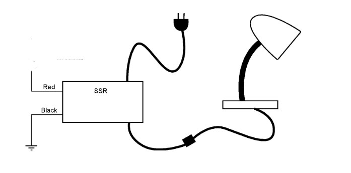
Now Connect up the red wire through your circuit board to an Arduino pin. Get the grounding working. Write a short subroutine to your physMenu to turn the light on or off using a button on the LCD shield.
- Diode Clipping Circuits (30 min)
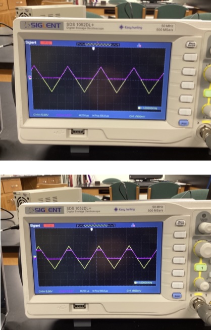
Drive each of the following circuits with a centered 14 V p-p triangle wave from a function generator. Look at the input and output voltages at the same time, with one probe each at $V_\text{in}$ and $V_\text{out}$ on your oscilloscope.
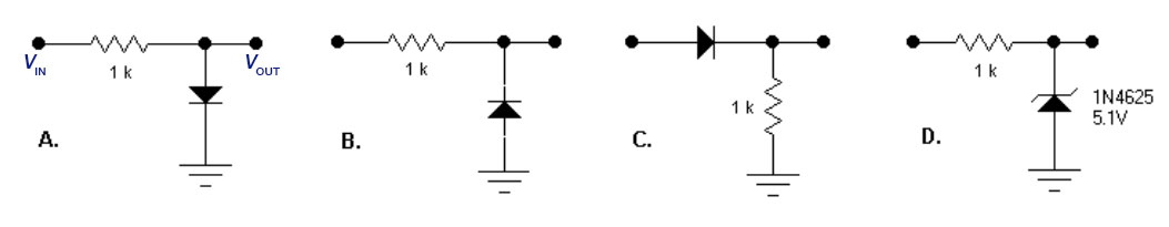
[added for 2025]For each circuit, include a snapshot of your scope trace and try to explain in a few sentences what is happening. Be sure you explain what is happening on the negative swings in B. Take a picture of the scope trace for B.On the negative swing the diode is actually conducting *from* ground to the input, because ground is higher (0) than the negative input voltage by more than 0.5 V when $V_\text{in}\lt -0.5$ V.
Zoey and Adrian's scope traces: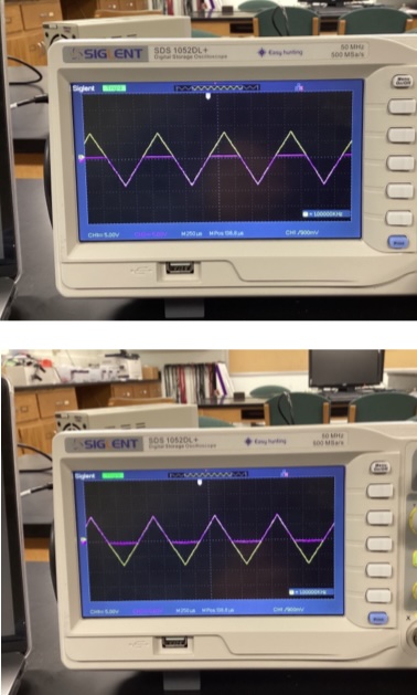
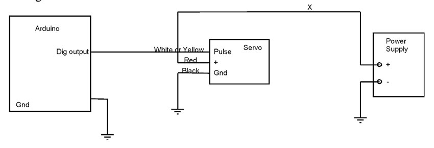
Use your servo routine from the prelab. Connect the Arduino to a servo. For the tiniest ones you may just use your Arduino 5V supply (just connect the wire labeled X to the Arduino 5V output. On the larger servos, you should use a separate supply set to 5 or 6 V as shown in the schematic below. This supply must still share a ground connection with the Arduino so that the supply has a common reference. Here is the wiring diagram for the servo connectors: