Lab 06
NO Pre-lab assignment!
Lab 06 - Op Amps & Audio Amplifiers
- Preliminaries. (10 min)
Look at the example board layout and aim to be as neat as possible. Orient your board as in the diagram. Use the top-most red rail (or "bus") for power and the bottom-most blue rail as your ground rail. Connect your power supply to your rails with red and black (ground) colored wires.
You also need to add bypass capacitors to your power supply rails. Use a couple .01 $\mu$F and one large value 100 $\mu$F or larger. Note that the large value capacitors have a polarity so look for a plus or minus and insert them the correct way.
- IR Phototransistor. (70 min)
Build the circuit below. The IR Phototransistor converts light into current. Provided it has a few volts across it, current will flow proportional to the IR light shining on it. The varying current flows through the 10 K resistor raising or lowering the voltage at A.
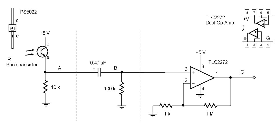
- Look at point A with the oscilloscope. See the effect of room light and shading on it. [2025]What is the frequency? Can you explain the frequency? The phototransistor is mainly sensitive to IR light but it also responds to visible light. Aim your remote control at it and press and hold the volume button (other buttons may not repeat). You may have to be very close to get a good signal. Can you see the strange code? Try different buttons and see what changes. Try to describe in general terms how the information is conveyed (is this an analog signal, is it digital pulses, what characteristics of it vary to carry the information?)
- Now look at the middle part of the circuit with the capacitor. This is called a high pass filter. It passes high frequencies while blocking low frequencies including DC. Look at A and B together on the scope. What are the average voltages at A and at B? Do you see how the DC component is gone at point B? Wave your hand around above the sensor and see how point B responds to changes at point A. Describe what the filter does: What does the voltage at point B do when the voltage at A changes?
- Now look at the right part of the circuit. This is a kind of amplifier made from the TL2272 op-amp. This op-amp works with power supplies anywhere from 4 to 22 V and its inputs and output work right down to the negative supply (ground in this case). What kind of circuit is this? What gain is this supposed to have? Compare B and C, does it give you exactly the expected gain for all signals? If not, why not?
- Describe how you might use this circuit and your remote control to make an Arduino project start or stop by pressing a button (any button) on the remote control. How would you connect this to the Arduino and what program code line or lines would make it happen?
- What if we had not used the high pass filter in the middle but simply connected the signal at point A to the op-amp circuit directly? You may try this if you like. Why does this not work?
- Microphone Amplifier. (30 min)
You can take apart the previous circuit.
Note that this circuit uses a different chip and the pins do not have the same functions. (This LM386 is an "audio amplifier"...an op-amp with the outside resistors built-in to give a gain of about 50.)
Use a 10 K linear (not audio) potentiometer from that earlier lab. Start by just building the left part of the circuit up to C.
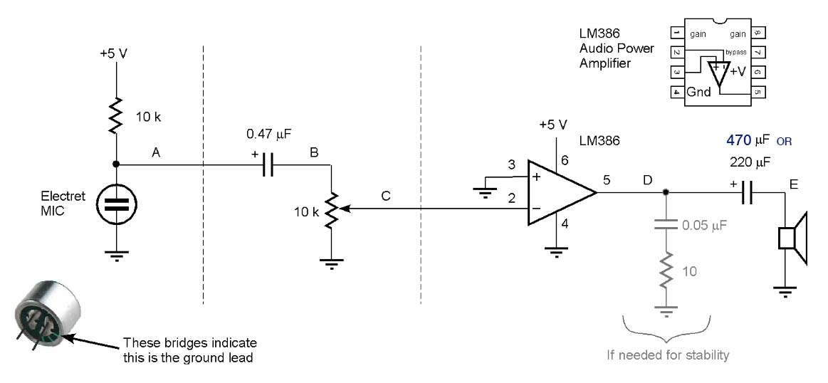
- Look at point A with the scope and try to see a signal when you clap or say x82ahhx82 very loudly or whistle.
- Next look at the second part of the circuit (itx27s another high pass filter but with an output that can be adjusted). Look at points A and B. How is the signal changed from A to B? Looking just at B, you can expand the scale and see the signal better. Try singing and whistling.
- Look at B and C while you have some steady noise as you turn the knob. What does the knob do?
- Now build the rest of the circuit. This last part is an audio amplifier circuit. The LM386 is not really a normal op-amp, it has internal feedback that already sets the gain at 20. So you donx27t need any feedback resistors.
- With the volume knob somewhere in the middle, try brushing your finger across the microphone element and see if you hear anything. Try blowing on the mic, or whistle into it.
- Look at the signal at D and at E on the scope. What is the average level at D? Why canx27t this signal be directly connected to the speaker? What does the capacitor do?
- Audio Amplifier. (30 min)
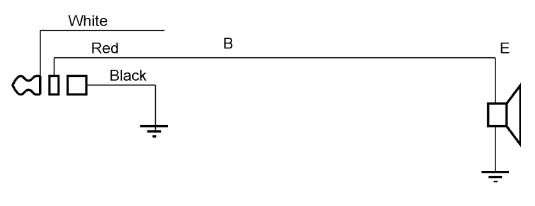
Remove the 0.47 $\mu$F capacitor from the previous circuit (to disconnect the microphone) and instead connect an audio cable to that point as shown below
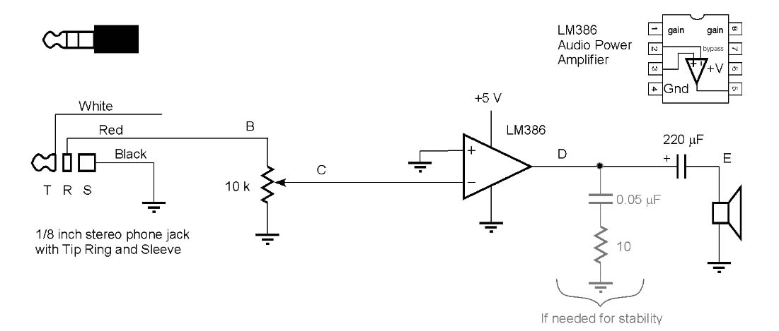
- Turn the volume knob toward the grounded end. Then plug your audio cable into the headphone jack of some audio device like an iPod. Set your device to play some music and slowly turn up the volume.
- You should find that if you try to set the volume moderately quiet, your volume control does not work well. Whatx27s wrong with it? Your instructor will show you a better one for this purpose.
- Compare the signals at B and E and adjust the volume until they are the same amplitude. Describe what is happening in the two parts of the circuit.
- (if time permits) Compare the circuit above (with the volume set so the output equals the input) with the much simpler circuit below. It just substitutes a wire for the whole circuit so that the output equals the input. Try it out but be a bit careful how you do. Before you connect a wire from B to E, you must first disconnect the old circuit from the speaker. This simpler circuit may or may not work depending on your audio signal source and your speaker. Why might it not work for some sources?