Capacitors
We have not really dealt with the time behavior of circuits very strictly. With resistors and batteries there is little time dependence to worry about.
But capacitors are used to make circuits that deal with time, and time-varying signals. They can be used to:
- store charge, and deliver it later on (much like a battery).
- respond (differently) to slow or fast signals
- create a slowly changing signal for timing
.jpg)
>
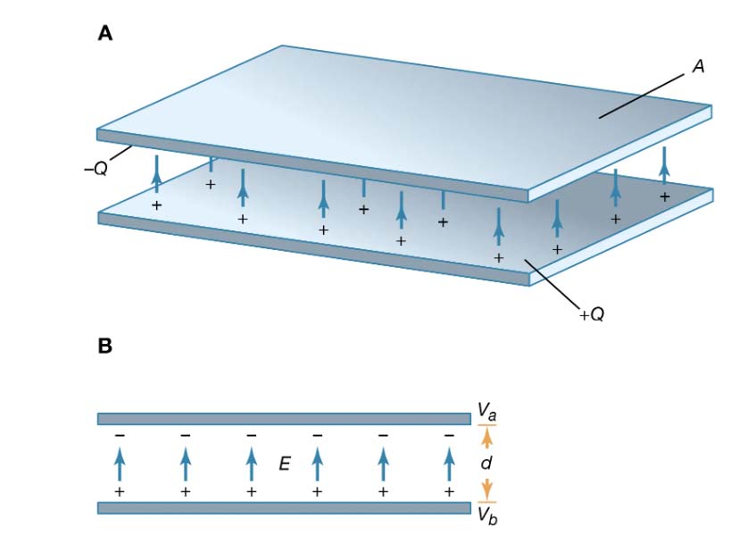
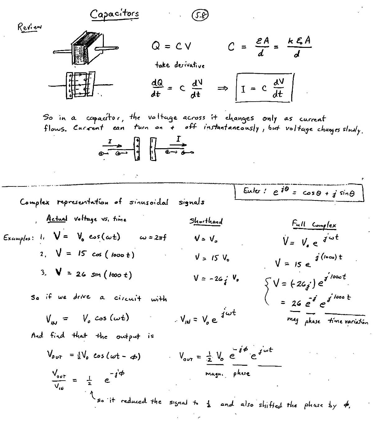
Capacitance, $C$ is a constant. It's the ratio of charge stored in the capacitor, $Q$ [units: Coulombs], to the voltage, $V$ across the plates of a capacitor. (So $V$ is the voltage drop across the capacitor.)
$$C=\frac{Q}{V}$$
In a capacitor, both the charge $Q(t)$ and the voltage $V(t)$ are functions of time. Writing the expression above as:
$$Q(t)=CV(t)$$
We can take the derivative with respect to time of both sides to get:
$$\frac{dQ}{dt} =C\frac{dV}{dt}$$
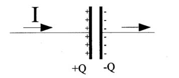
You might recall from some Physics class that $\frac{dQ}{dt}$ is the amount of charge passing some point in a wire, which means the same thing as the current, $I$ [Units: Coulombs/sec = Amperes!] So we have:
$$I=C\frac{dV}{dt}\ \ \text{or}\ \ \color{red}I\Delta t\color{black}=C\Delta V$$
...which is a way of saying, to change the voltage you need some combination of current and time.
Consider this circuit:
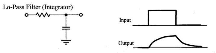
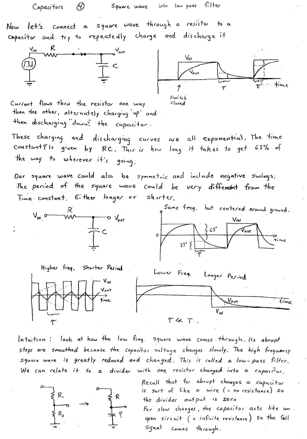
- When the current into the capacitor changes quickly, the capacitor responds quickly, somewhat like a wire, but unlike a wire, its voltage changes rapidly. (See steep positive and negative slopes in $V_\text{out}(t)$).
- But the longer the current flows, and charge has time to accumulate on the plates, the charge "pushes back" on the current and the voltage changes more slowly.
If we were to stretch out the time that the input is high and the time that the input is low, $V_\text{out}$ would look more and more like the input signal.
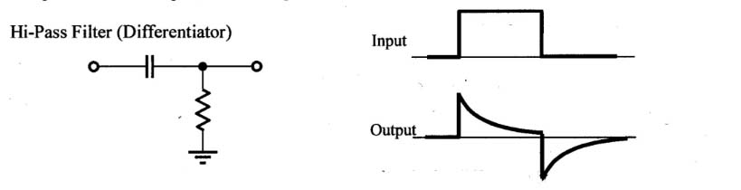
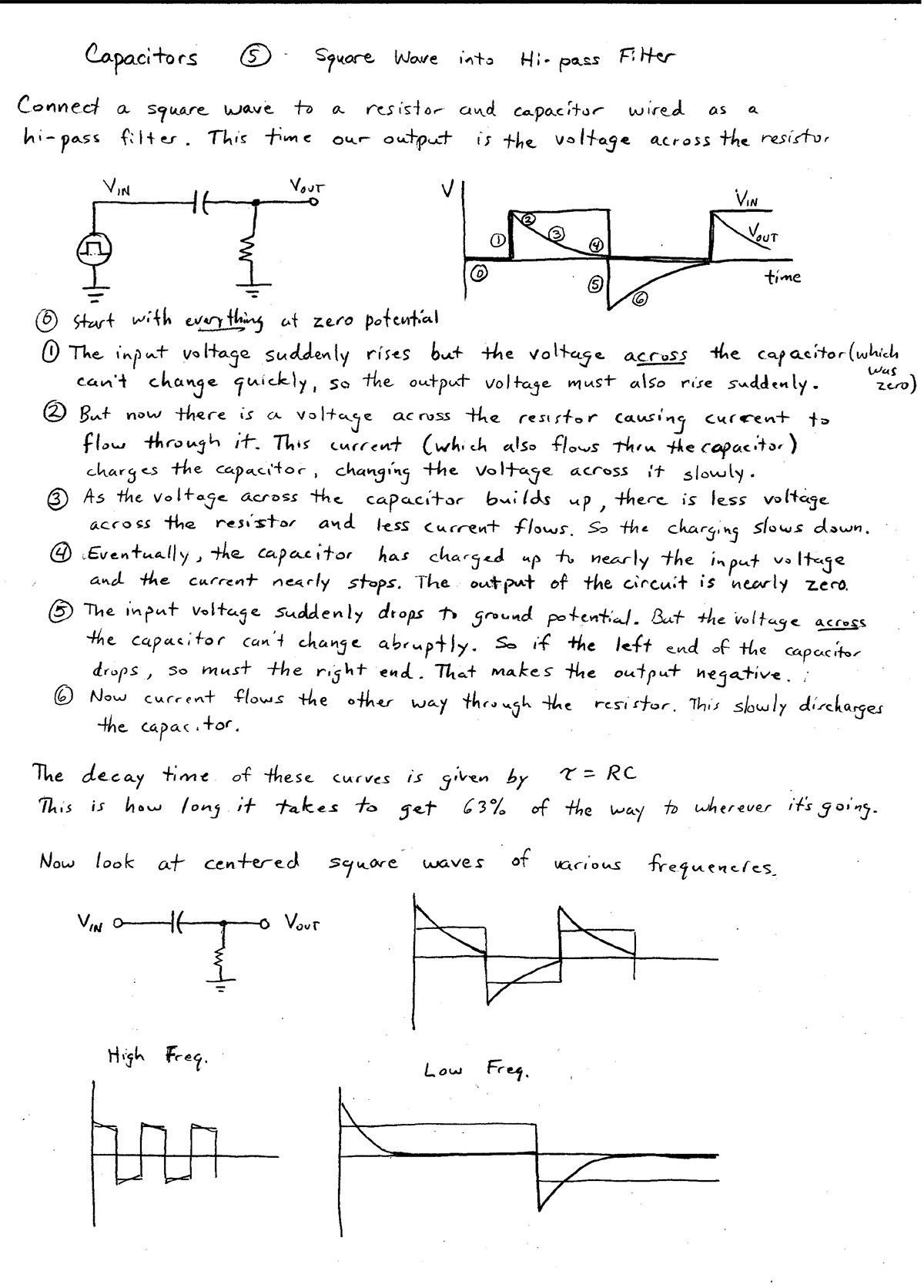
In this second circuit, when the signal voltage changes quickly, the capacitor responds once again in a "wire-like" manner, and quickly follows the voltage change. But as more charge accumulates on the plates, and the capacitor resists current flow, less and less current flows through the resistor so $V_\text{out}$ approaches 0. We could say that thatfor e x t r e m e l y slow changes, the capacitor allows no current flow through
much like a break in the wire (sort of the opposite of "wire-like" behavior").
For this "High Pass" filter, if we were to stretch out the the time that the input is high and the time that the input is low, we would no longer see the long term voltage levels, and would only see the spikes where the sudden changes happened.
Let's get mathy

magnitude of the complex quantity...
$\left|\frac{V_\text{out}}{V_\text{in}}\right| = \frac{1}{\sqrt{1+f^2/f_0^2}}=$Lo-Pass filter response [Desmos].
Decibels and logarithmic scaling
Multiplicative factor in decibels: dB=$20\log_{10}(x)$- $20\log_{10}(100)=40$ dB
- $20\log_{10}(10)=20$ dB
- $20\log_{10}(2)=6.0206\approx 6$ dB
- $20\log_{10}(\sqrt 2)\approx 3$ dB
- $20\log_{10}(1/\sqrt 2)\approx -3$ dB
Summary
Impedance of a capacitor
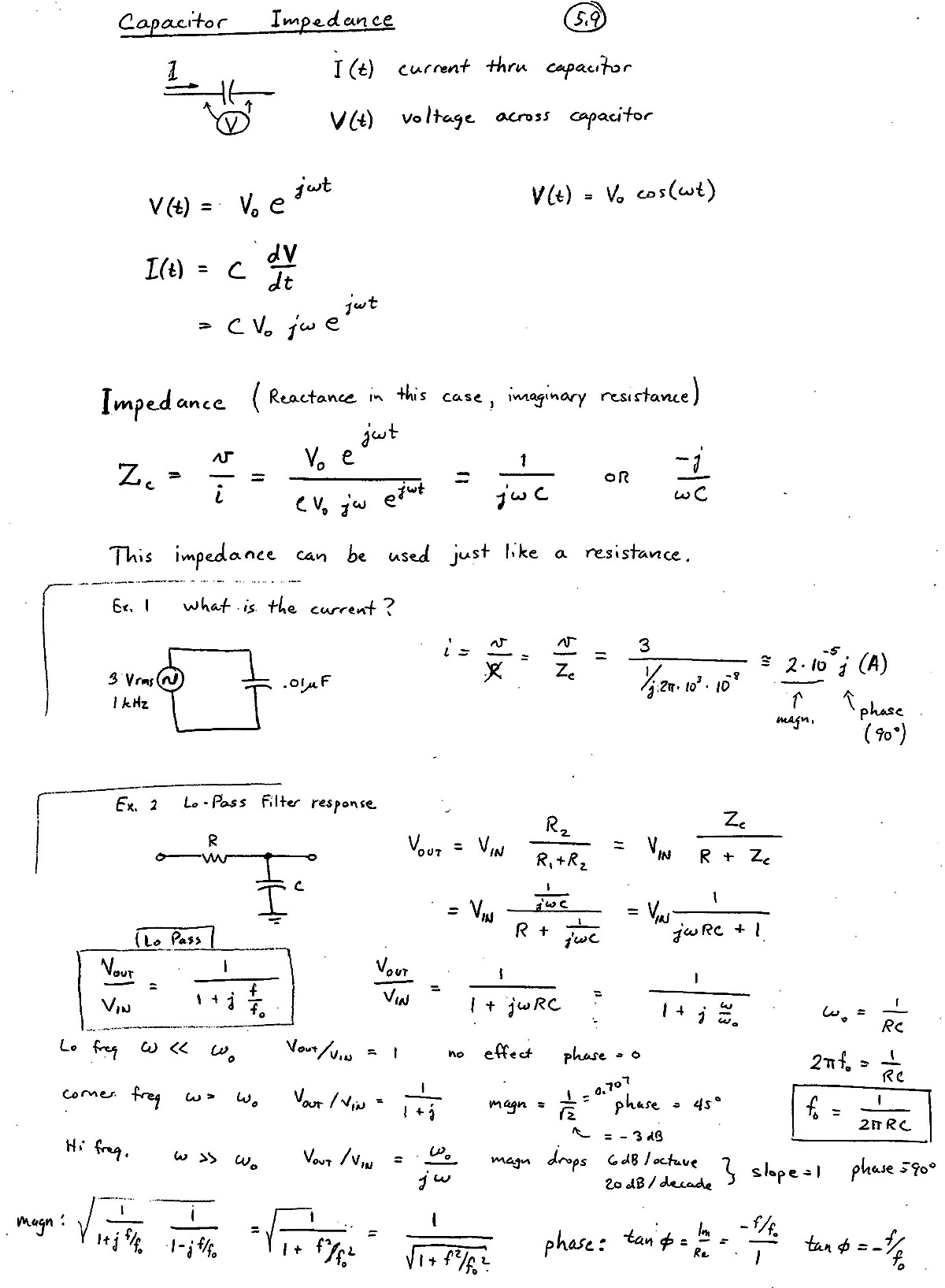
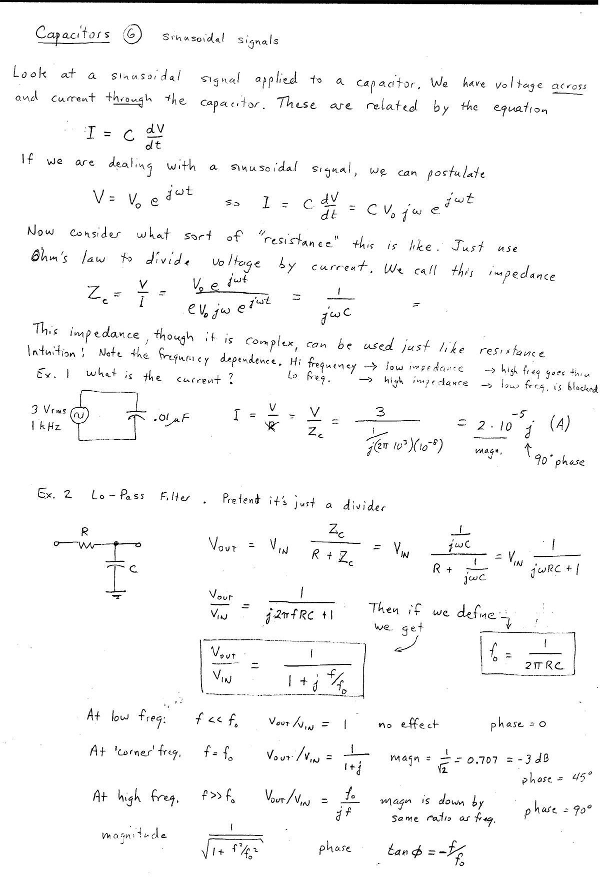
Impedance ($Z$) is like the resistance of a resistor: It's the ratio of voltage divided by current. Except it's a complex quantity: $$Z_c=\frac{V(t)}{I(t)}=\frac{V_0e^{j\omega t}}{CV_0j\omega e^{j\omega t}}=\frac{1}{j\omega C}.$$
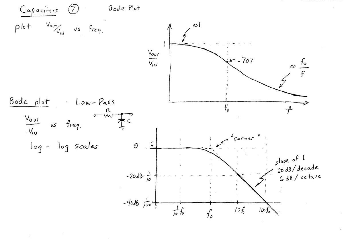
Low-pass filter
Viewing the low-pass filter as a "voltage divider", we calculate $V_\text{out}$
as
$$V_\text{out} = V_\text{in}\frac{Z_c}{Z_c+R}$$
So the ratio of output to input voltage is:
$$\frac{V_\text{out}}{V_\text{in}} = \frac{R}{Z_c+R}$$
Now, let's separately look at the magnitude and the angle (or phase angle) of this complex number. The magnitude of this ratio is what we plot on a Bode plot. Recall that a complex number can be written in two ways:
$$Z=Re^{i\phi} = X+ iY.$$
The magnitude of any complex number is the same the length of the vector in complex space, which is the square root of the number times its complex conjugate:
$$\begineq |Z| = \sqrt{Z Z^{*}}=\sqrt{Re^{i\phi} Re^{-i\phi}} &=\sqrt{(X+iY)(X-iY)}\\
\sqrt{R^2e^{i\phi}e^{-i\phi}}=\sqrt{R^2e^{i\phi-i\phi}}
&=\sqrt{X^2+iYX-iXY -i^2Y^2}\\
\sqrt{R^2e^0}=\sqrt{R^2}=\color{blue}R
&=\color{blue}\sqrt{X^2+Y^2}\\
\endeq
$$
So the magnitude of the ratio of output voltage to input voltage is: $$\begineq \left|\frac{V_\text{out}}{V_\text{in}}\right| &= \left|\frac{Z_c}{Z_c+R}\right| =\left|\frac{1}{1+R/Z_c}\right|\\ &=\left|\frac{1}{1+j\omega RC}\right| = \left|\frac{1}{1+j2\pi fRC}\right|\\ &=\left|\frac{1}{1+jf/f_0}\right|\\ &=\color{blue}\frac{1}{\sqrt{1+(f/f_0)^2}}\\ \endeq $$ Where I've defined the constant $f_0=\frac 1{2\pi RC}$.
At high frequencies $f/f_0$ is much greater than 1. So we can approximate the ratio as $$\left|\frac{V_\text{out}}{V_\text{in}}\right| \approx \frac{1}{\sqrt{(f/f_0)^2}}= \frac{1}{f/f_0}= \color{blue}\frac{f_0}{f}. \label{highf}$$
On a Bode plot (a log-log plot), the $x$ and $y$ axes are: $$x\equiv\log f \ \ \ \text{and} \ \ \ y\equiv\log\left|\frac{V_\text{out}}{V_\text{in}}\right|$$ Taking the log of both sides of the high-frequency limit in Eq $\ref{highf}$, we have: $$\begineq \log\left[\left|\frac{V_\text{out}}{V_\text{in}}\right| \right] &= \log(f_0/f)=\log(f_0) -1\cdot\log(f) \\ y &= [\text{a constant}] -1\cdot x \endeq $$ So, the graph of the voltage ratio on a log-log plot of the high frequency limit will be a straight line with a slope of -1.
The phase difference angle, $\phi$ between the input and output voltage is the phase of the complex number $Z=X+iY=Re^{i\phi}$, which we can find from the polar angle relationship $\phi=\arctan\left(\frac YX\right)$. So, we must separate our voltage ratio into its real part and imaginary part: $$\begineq \frac{V_\text{out}}{V_\text{in}} \\ &= \frac{1}{1+jf/f_0}\cdot\frac{1-jf/f_0}{1-jf/f_0}\\ &= \frac{1}{1+(f/f_0)^2}\cdot\left(1-jf/f_0\right)\\ \endeq $$ So, our phase angle is $$\phi=\arctan\left(\frac YX \right)=\arctan\left(\frac {-f/f_0}{1}\right)= \color{blue}\arctan\left(-\frac{f}{f_0}\right) $$
High-pass filter
Viewing the High-pass filter as a "voltage divider", we calculate $V_\text{out}$
as
$$V_\text{out} = V_\text{in}\frac{R}{Z_c+R}$$
$$\begineq \left|\frac{V_\text{out}}{V_\text{out}}\right| &= \left|\frac{R}{Z_c+R}\right|
=\left|\frac{1}{1+Z_c/R}\right|\\
&=\left|\frac{1}{1+1/(jf/f_0)}\right| =\left|\frac{1}{1-jf_0/f}\right|\\
&=\color{blue}\frac{1}{\sqrt{1+(f_0/f)^2}}\\
\endeq
$$
And the phase angle difference is:
$$\phi = \color{blue}\arctan\left(\frac{f_0}{f}\right).$$
As before, $f_0=\frac 1{2\pi RC}$.
Units of $RC$
We had $$Q=CV$$
- Charge, $Q$, has units of coulombs.
- Voltage, $V$ has units of volts
So capacitance, $C$ must have units of coulombs / volt $\equiv$ "farads".
What about $\color{red}RC$? Since $R=V/I$, we conclude that one ohm = one volt$\cdot$sec/coulomb.
So units of $RC$ are $${\text{ohms}}\cdot{\text{farads}} =\frac{\text{volt}\cdot\text{sec}}{\text{coulomb}}\cdot\frac{\text{coulomb}}{\text{volt}} =\color{blue}\text{seconds}$$
...and if $RC$ has units of seconds, then $f_0=1/(2\pi RC)$ has units of 1/seconds, as a frequency should.