Lab 02: Menu & Oscilloscopes
Using the LCD display shield you assembled last week, you'll upload a pre-written program onto the Arduino that puts a menu on the LCD screen, and allows you to use the arrow buttons on the display shield to select and execute one of the subroutines associated with each menu item.
Pre-Lab Assignment
Typically each time you connect a new shield or other device to your Arduino, you will also download a library that allows your programs to connect and interact with the new device. A library is a collection of C subroutines and objects that your program can call on.
We'll use the new LCD shield that you asssembled to allow your programs to display and implement a menu on the LCD shield that can be used to control the Arduino when disconnected from a computer.
-
Use the Arduino Library Manager to install a library for the board you soldered together last week:
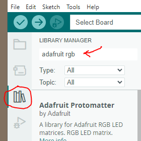 In the Arduino IDE, open the Library Manager: It's an icon at the left that looks like books on a shelf.
Then, search for the Adafruit RGB LCD Shield Library. Select and install.
In the Arduino IDE, open the Library Manager: It's an icon at the left that looks like books on a shelf.
Then, search for the Adafruit RGB LCD Shield Library. Select and install.
(There are a number of similar-sounding libraries which will *not* work. E.g. avoid the Adafruit TinyRGBLCDShield library.)
This contains the low-level functions you'll use to interact with the display shield.
- Next, you'll install a custom library, written at GC. It's a C "object" designed to run a menu object called
mon the LCD-shield.- On our website, go to resources/Libraries/physMenu. Download the 3 files you see there. E.g. in Chrome, you would right-click on each file and choose Save Link As.... On a PC, they'll end up in your /Downloads/ folder.
- Navigate to This PC / Documents / Arduino / libraries. You should see a folder for the LCD shield library you just added. There's more documentation about where to put your custom libraries at docs.arduino.cc/hacking/software/Libraries.
- Make a folder called physMenu, and move the 3 files you downloaded into that folder.
- Check that it worked: Quit the Arduino IDE. Start it up again, and go to Sketch | Include Library. You should see 'physMenu' as an option under 'Contributed Libraries'.
- Download the PhysicsMenu1.ino program from our resources/SketchesMenus folder. Put this wherever you are putting your Arduino sketches (programs). By default, this is This PC / Documents / Arduino.
Just save the .ino file in that folder. In the IDE do File | Open and click on the physMenu1.ino file. The IDE will scold you to put it inside a folder, and offer to do that for you, and you should do that. - Try "Check"ing the PhysicsMenu1 without connecting it to a board. (Though you will need to specify the "Arduino Uno" as your board...) If all the libraries are available, you should not get any error messages.
- Now connect your display shield (or one of the ones from past years on the SC008 countertop) to your Arduino board. Everything should work. The up and down arrows scroll through the menu items. The select button runs that item and then returns to the menu. In some cases there is more to do in the item and you must use the left button to get back to the menu again.
If you don't see anything on the LCD display, try turning the adjustment pot on the board one way or another. - Look through the PhysicsMenu1 program. You should see that each menu item is "registered" with the
mobject, and refers to one of the named subroutines. Try adding your own function. Start VERY simple with just a couple lines. To add a new menu option you must do the following: Add a line like the following to the others in setup. m.addItem("7 Short Flash ", &shortFlash); Write your new program as a function at the very end of the existing code:// Do Nothing Function -------------- void doNothing() { m.lcd.clear(); delay(500); } // Your New Function (this is a short flash example) ------------ void shortFlash() { // m.lcd.clear(); m.lcd.print("Brief Flash"); pinMode(13,OUTPUT); digitalWrite(13, HIGH); // set the LED on delay(200); // wait for a bit digitalWrite(13, LOW); // set the LED off }
Add your own function to PhysicsMenu1.h and see if you can get it to work. Copy and upload your modified version of PhysicsMenu1.ino.
If you got stuck along the way, write about the last thing you tried and what happened.
Lab 02: Menu & Oscilloscopes
Lab notebook / Notability on iPad
 Today we'll use Notability as a "Lab Notebook" to write down your observations and document what you do in the lab. Notability let's you take photographs (and scale and crop them in your Note), draw (with a finger or stylus), write text, and more.
Start a new Note for today's lab. You'll eventually hand in a pdf version of your notebook file. You only need to hand in one pdf per lab team--with both partners' names on it!!--but you should both keep notes for your own reference later on.
Here is the orientation to Notability for our class.
Menu Template (~40 min)
(From the PreLab) Carefully put an LCD Shield onto one of your Arduinos. Upload the physicsMenu1 program and see that it all works properly. Be sure to check the buttons. Explore the new template menu a bit. Upload your new program which consists of the physicsMenu with an extra function (menu item) added to it.
- Get all your functions working.
- Demonstrate your new function to your instructor.
- Make sure your new code is well commented. (You *did* put comments in your code of course!)
- Copy the code for your new function and paste it into your lab note. (If you declared any global variables print that section too.)
Oscilloscopes
- Function Generator and Oscilloscope Game (30 min)
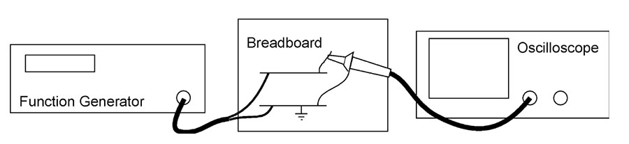
Connect a function generator's output to a point on the breadboard and to a ground and then use a scope probe to look at the same point as shown.
Function Generator: Start with the function generator set to a triangle wave, 1000 Hz (=1000 cycles / sec), output amplitude near the mid point of the knob's range.- BK Function Generators: Be sure the amplitude knob and the offset knob are pushed in.
-
Pasco Generators: Use the banana-plug-to-BNC adapter to span Hi$\Omega$and GND for the output for now. Make sure the side of the banana plug adapter labelled GND is plugged into GND!.
Oscilloscope: Turn it on with the power button on top. Then adjust the horizontal scale (big knob) until the display shows the triangle wave.
- Tektronix TDS 210: Adjust SEC/DIV until the display reads 500$\mu$s.
Your lab instructor will give you more info about the controls such as: What does the coupling do? What does the X10 on the probe mean? What does the triggering do?
Take turns creating a strange signal (vary the amplitude, the offset (Pasco only) and the frequency) with the function generator. Then let your partner get a good display of it on the scope and read its vital signs (frequency, amplitude, offset) without seeing the generator controls.
Trade places and repeat the exercise.
- Voltage Divider AC (15 min)
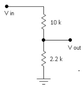 Use the signal generator as the input to this divider circuit that
you've assembled on your breadboard. Look at this with the
oscilloscope but use two probes. Connect the Ch 1 probe to the input
and the Ch 2 probe to the output so you see both signals at the same
time. Turn on both channels (the channel buttons do this) Set trigger
to Ch. 1. Put the input channel in the upper half of the screen and
the output on the lower half.
Use the signal generator as the input to this divider circuit that
you've assembled on your breadboard. Look at this with the
oscilloscope but use two probes. Connect the Ch 1 probe to the input
and the Ch 2 probe to the output so you see both signals at the same
time. Turn on both channels (the channel buttons do this) Set trigger
to Ch. 1. Put the input channel in the upper half of the screen and
the output on the lower half.
Take a picture of the scope trace display for your note. Label the signals and the scales. Also make a drawing of the schematic circuit diagram.
Take a picture capturing mostly just the display. Someone should be able to read the on-screen division sizes from the display in your picture.
Using our divider result: $$V_\text{out}=\frac{R_2}{R_1+R_2}V_\text{in} =\frac{2.2\text{ K}}{12.2\text{ K}}V_\text{in}\approx \color{blue}\frac 16 V_\text{in}.$$ So the p-p output voltage should be 1/6 of the p-p input voltage.We did not have a good handle on the oscilloscope settings. So if your ratio $V_\text{in}/V_\text{out}~6\times 10^n$, great!
More generally, if...
- $V_\text{in}\to V_t$, the voltage at the top of the divider,
- Instead of the the voltage at the bottom being grounded, 0 V$\to V_b$
- Then the voltage drop across $R_2$ is $V_\text{out}-V_b$...
Variable Divider (20 min)
Ask for an introduction to variable resistors and how they are made. Be sure you understand which rotation direction moves the wiper toward which of the terminals. Use a 10 k$\Omega$ (usually just written: 10 k) variable resistor (also called a potentiometer, pot, or rheostat) to build the circuit shown.
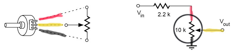
Connect the input to your signal generator. Observe the input and output with your scope as you turn the knob of the pot. Your pot is connected as a variable voltage divider. See if you can get the output to be exactly half the input.- What must be the resistances in the two parts of the pot in this case?
- What sort of output do you get when the pot is turned to each extreme position?
One way you should see $V\text{out}\to 0$.
The other way you should see $V\text{out}\to \frac{10K}{12K}V\text{in}=\frac{5}{6}V\text{in}$. - Sometimes you just want a single resistor to have a variable resistance. In other words you want a device with only two leads. How could you use the potentiometer for this situation? In other words, if you just wanted to add a variable resistance of 0 to 10k between two points in a circuit, which of the leads of the potentiometer would you connect to? What would you do with the third lead? (Make a sketch...)
The resistance across either yellow-red or yellow-black should vary between 0 and 10 K.
Optional (if you have time): Get an Audio Taper pot and put it in place of your Linear Taper pot. Put this in a circuit like the above and look at the output on the scope as you turn the knob. Can you see the difference in the behavior? Why would this be used for audio things?
- Loading the Signal Sources ( 15 min)
Four options for the signal source, try to do all four:
- Use the BK Generator,
- Use the Pasco Generator Hi$\Omega$ and GND,
- Use the Pasco Lo$\Omega$ and GND.
- Use the Arduino beeper output.
Without using any voltage divider, just connect your source (one of the four) to the oscilloscope Ch 1. While the output of the source is displayed on the scope, connect a 2.2 k resistor from the signal to ground. Do you see any change in the signal as the resistor connection is made (try connecting and disconnecting the resistor while watching the scope)?
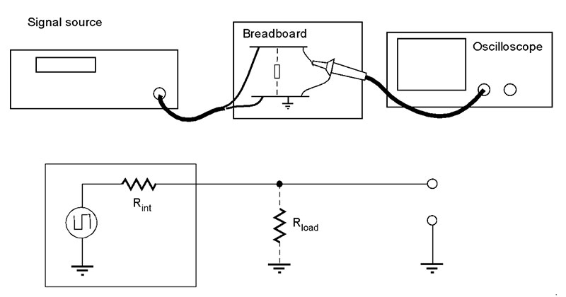
Try a lower resistance (we'll provide a a 100 $\Omega$ resistor). What does this suggest about the source's output? Write down what you directly observe (including a schematic) in all cases and then what you conclude (your observations should be straightforward and clearly recorded, your conclusions may be confused).
More about this in class!
Export your Note from today to a pdf and hand that in--one per team with all names!