Operational Amplifiers (Op Amps)
An operational amplifier (op-amp) is a high-gain, analog voltage amplifier.
The voltage at the output $V_\text{OUT}$ is some multiple, $M$ of the difference between the two inputs, $(V_+ - V_-)$:
$$V_\text{OUT} = M(V_+-V_-),$$
where $M$ might be 100,000 or more. But The exact multiplier, $M$ hardly matters.
This turns out to be...

Cole Henley
Op-amp principles, and common circuits
- $V_+$: Non-inverting input
- $V_-$: Inverting input
- $V_\text{S+/-}$: Positive and negative Supply voltages
The two principles of how op amps behave in a circuit:
- If there is any feedback (electrical connection) between $V_\text{OUT}$ and either of the inputs, the output voltage will not rest unless the two inputs are within 1/$M$ of each other. And since $M$ is very large, the two inputs would have to be essentially equal.
- The two inputs are designed to have very high impedance. (Higher than any impedance in the circuit it's a part of). So, ideally no current flows in or out of the inputs
Non-inverting amplifier
- By rule #2, no current flows into $V_-$
- So all the current that flows through $R_f$ flows through $R_g$ too.
- See the voltage divider?
- By rule #1, $V_- = V_\text{in}$,
- and therefore (...algebra:) $$\begineq V_\text{in} &= V_\text{OUT}\frac{R_g}{R_g+R_f}\\ V_\text{in}\frac{R_g+R_f}{R_g} &= V_\text{OUT}\\ \color{blue}V_\text{in}\left(1+\frac{R_f}{R_g}\right) &= \color{blue}V_\text{OUT}\\ \endeq $$
- Quick! select $R_f$ and $R_g$ such that the $V\text{OUT}= 7\times V_\text{in}$.
- Should we pick high values of the two resistors or low values?
So, by selecting appropriate resistors outside of the op-amp, we can quickly construct a circuit to amplify a signal with any gain that we choose!
The input impedance of this circuit is the input impedance of the $V_\text{in}$ op amp input: $Z_\text{in}\to \infty$.
Pulling current out of the output doesn't change the "goal" (keep $V_- = V_\text{in}$) of the op amps. So $Z_\text{out}\to 0$. (Though eventually, there is a maximum current limit.
Follower
 Consider this circuit...
- Can you surmise (hint: rule 1...) what the gain of this circuit is?
Now, consider this circuit as just a variation on the non-inverting amplifier..
- What is $R_f$?
- What is the (effective) $R_g$, the resistance connecting the voltage divider to ground?
- Calculate the gain from our formula above...
- What is the output impedance?
The (powered) Op Amp tries to do whatever it takes to keep its inputs at the same voltage.
If a low resistance load at the output starts to draw down the voltage at the output, the output should boost the current to its output to bring the voltage higher.
An ideal op amp has an output impedance approaching 0: $$\color{blue}Z_\text{out}\to 0.$$ But beware, eventually there is a maximum current that an op amp is capable of sourcing. Typically of order $\pm 25$ mA.
You could put this circuit between a high impedance signal source and a low impedance load...
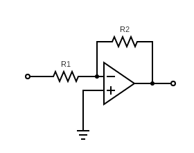
Inverting amplifier
Let's analyze this one...
 >
>
- What must $V_-$ be?
- So what current is flowing through $R1$?
- Is current flowing into $V_+$...No! So where must the current through $R1$ go?
- What must $V_\text{OUT}$ be, to keep the appropriate current flowing?
- OK, now we have should have $V_\text{OUT}$ in terms of $V_\text{in}$... what is the gain?
- Input and output impedance?