Capacitor worksheet
Here is the capacitor worksheet
Consider the phase shifts in these scope traces of yours (.pdf)
I suggest...
...that you calculate the values in the table in #2 first and graph the points. Then come back to #1, where you graph the "corner frequency" point, and two lines for the high- and low-frequency limits. (See the new discussion of the high-frequency limit for a low-pass filter in the capacitor notes.)
More on the individual worksheet questions
- On this graph, the $x$ values represent the log of the frequency, $\log(f)$
and the $y$ values represent the log of the voltage ratio,
You can sketch the Bode plot *just* by calculating $f_0$: Start by graphing the "corner frequency" point $(f_0,1)$. Then, draw two lines through this point:
- In one direction, the ratio of voltages approaches 1, independent of frequency. so draw a horizontal line through the corner frequency point.
- In the other direction, it depends on whether you have a high- or a low-pass filter.
- The high frequency limit for a low-pass filter is a straight line with a slope of -1 running through that "corner frequency" point.
- The low-frequency limit for a high-pass filter is a straight line with a slope of +1 running through that "corner frequency" point.

-
In class example using the results in the notes for the high-pass filter, for the $f=3$ Hz row:
- Calculate $f_0$:
$$f_0=\frac{1}{2\pi R C}$$
- $R=$4.7 kOhms= $4.7\times 10^3$ Ohms.
- $C=0.1\mu$F =$0.1\times 10^{-6}$ Farads.
- 1 Farad $\cdot$ 1 Ohm = 1 second
- The time constant $\tau$ for exponential decay for a simple RC circuit is $$\tau=RC=4.7 \times 10^3\cdot0.1\times 10^{-6}=0.47\times 10^{-3}$$ So, $\tau =$ 0.47 milliseconds.
- $2\pi R C$ = $2\pi\cdot0.47$ milliseconds = 3 milliseconds = 0.003 seconds.
- $f_0=1/(0.003 s)=\color{blue}333$ Hz.
- Calculate $|V_\text{out}/V_{in}|$ (decimal)
For a high-pass filter... $$\left|\frac{V_\text{out}}{V_\text{in}}\right| = \frac{1}{\sqrt{1+(f_0/f)^2}}= \frac{1}{\sqrt{1+(333/3)^2}}=\color{blue}0.0090 $$
- Calculate $|V_\text{out}/V_{in}|$ (in decibels)
Using our decibels conversion, the magnitude of our voltage ratio in decibels is $$20\log_{10}\left(\left|\frac{V_\text{out}}{V_\text{in}}\right| \right) = 20\log_{10}(0.0090)= \color{blue}-41\text{ dB}. $$
20 decibels is a factor of 10. So, -20 dB is a 1/10=0.1 and -40 db is 1/100=0.01. 0.009 is just a little bit smaller than 0.01, and -41 dB is just a little lower than -40 dB.
- Phase angle difference
The phase angle difference for a high-pass filter in radians is: $$\phi=\arctan(f_0/f) = \arctan(333/3)=1.562\text{ radians}=\color{blue}89.5{}^o.$$
- Calculate $f_0$:
$$f_0=\frac{1}{2\pi R C}$$
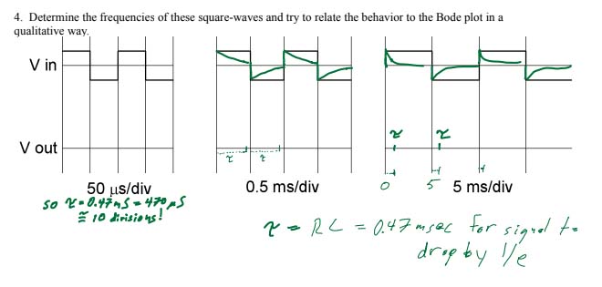
- On number 4, you'll use the idea that the exponential for an RC circuit has an exponential decay of $e^{-t/\tau}$. So $\tau=RC=0.47$ msec is the time it takes for the exponential to decay to $e^{-1}\approx 0.37$=37% of its starting value.